


-
CN0549 User Guide10/28/2020WIKI
Overview
Design Resources
Design & Integration Files
- Schematics
- Bill of Materials
- Gerber Files
- Assembly Files
- Allegro Layout Files
Evaluation Hardware
Part Numbers with "Z" indicate RoHS Compliance. Boards checked are needed to evaluate this circuit.
- EVAL-CN0532-EBZ ($88.28) IEPE-Compatible Interface for Wideband MEMS Accelerometer Sensor
- EVAL-CN0540-ARDZ ($176.55) 24-Bit Data Acquisition System for IEPE Sensors
- EVAL-XLMOUNT1 ($100.05) Mechanically optimized mounting block for MEMs accelerometer boards
Device Drivers
Software such as C code and/or FPGA code, used to communicate with component's digital interface.
FPGA/HDL
Features & Benefits
- Wide bandwidth MEMs accelerometer sensor data is output in the popular IEPE format
- Easy mounting to machines (like pumps, fans, and motors) while maintaining sensor signal integrity
- The DAQ solution provides a high fidelity, IEPE analog input bandwidth from DC – 54 kHz
- Embedded FPGA Software captures and stores the raw data for local embedded or networked processing
- IIO Oscilloscope application allows users to quickly visualize the data for evaluation purposes.
Markets and Technologies
Parts Used
Documentation & Resources
-
CN-0549: IEPE-Compliant, CbM Machine Learning Enablement Platform (Rev. 0)10/28/2020PDF370 K


-
High Fidelity Vibration Acquisition Platform for Condition Monitoring8/13/2021
-
Open-Source, Reusable Software Stack Enables Real-Time Processing and Algorithm Development for CbM8/13/2021
-
Why MEMS Accelerometers Are Becoming the Designer’s Best Choice for CbM Applications2/1/2021
-
How Sensor Performance Enables Condition-Based Monitoring Solutions6/1/2019 Analog Dialogue
-
Condition Based Monitoring (CbM) using MEMS Accelerometers3/23/2022
-
Accelerate Smart Manufacturing with complete system level solutions for condition monitoring and robotics motion control from Analog Devices4/14/2021
-
Condition-based Monitoring (CbM) Development Platform, from Vibration Sensing to Algorithm Development1/19/2021
Circuit Function & Benefits
Machine condition-based monitoring (CbM) by means of vibration sensing is growing in importance in industrial applications. Companies are seeking to optimize machinery lifetime and performance and to reduce the cost of ownership, while some are looking to develop new business models around the provision of such information. To provide an accurate representation of machinery that needs monitoring, large datasets must be collected to determine a baseline operating point for the equipment in both normal operating modes and failure conditions. Once this data is collected, an algorithm or threshold detection routine can be created to provide the correct analysis for this equipment.
CbM requires capturing full bandwidth data to ensure that all harmonics, aliasing, and other mechanical interactions in both the time and frequency domain are accounted for. This data collection requires a high performance sensor and data acquisition (DAQ) system that can provide high fidelity, real-time data into a data analysis tool or application.
Using established tools like MATLAB® or newer Python-based tools like Tensorflow, analyzing the data, profiling the machinery, and creating algorithms for smart decision making is greatly simplified.
Vibration sensing has traditionally dominated most CbM applications because of the availability of sensors, and the science behind the analysis is better understood. The integrated electronic piezoelectric (IEPE) standard is a popular signaling interface standard for high end microelectronic mechanical systems (MEMS) and piezo sensors that are prevalent in the industry today.
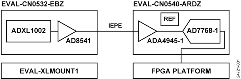
Figure 1. CN-0549 System Block Diagram
Circuit Description
Vibration Analysis
Vibration sensing has traditionally dominated most CbM applications because of the availability of sensors, and the science behind the analysis is better understood. However, what if a new piece of equipment needs analyzing, or a need to better understand how a particular use case affects equipment arises. To gain the necessary insights, first an understanding of how the machinery behaves when working in optimal conditions and in failure inducing conditions is required. Figure 2 provides an example of what a frequency spectrum might look like when operating with a vibration source.


Vibration Sensors—IEPE Interface
IEPE is a popular interface standard for high end, piezo vibration sensors that are prevalent in the industry today. The IEPE interface is a 2-wire signaling standard that consists of a signal and ground only. A DAQ card, such as the CN-0540, supplies power via the signal line to the CN-0532 vibration sensor as current with an arbitrary voltage, typically between 10 V to 30 V. Because the signal line is supplied by a current source, the sensor device can modulate the acceleration data on the voltage rail. Therefore, a single wire can be used for both the power supply and the modulated output voltage of the sensor.
MEMS vs. Piezos
Piezo accelerometers dominate the CbM market today because of their wideband frequency response and sensitivity to vibration stimuli. However, with recent advancements with MEMs technology, the gap between piezos and MEMs accelerometer sensors are closer in performance than ever before.
The CN-0532 IEPE MEMs vibration sensor is based on the ADXL1002. The noise and bandwidth is comparable with a piezoelectric sensor while the ADXL1002 provides superior performance in temperature sensitivity, dc to low frequency response, phase response (and thus, group delay), shock tolerance, and shock recovery. The sensor has a linear (within ±0.1% full-scale ratio (FSR)) measurement range of ±50 g, which is large enough to support a wide array of vibration applications. For more information about the ADXL1002 and how it is used in an IEPE interface, visit the CN-0532 web page.
When using the CN-0549, it is possible to directly compare piezo sensor performance with that of a MEMS-based sensor solution.
Mechanical Sensor Mounting
A major challenge for CbM applications is trying to bridge the analog and digital worlds. Getting dependable sensor data from the machine being monitored into the processor is challenging. First and most importantly, a connection between the sensor and the piece of equipment being monitored must be established. Once attached to the piece of machinery, it is important to ensure that the vibration spectrum is not altered by any mechanical anomalies or effects due to the mounting of the sensor.


The EVAL-XLMOUNT1 is a five sided mounting cube that allows a user to attach the CN-0532 to a piece of equipment without any sensor degradation to data. The EVAL-XLMOUNT1 was designed and tested to ensure that all error sources due to the mechanical attachment have been removed out to a frequency of 20 kHz. The mounting cube was also anodized to form a nonconductive layer on the aluminum surface to prevent short circuits.
Data Acquisition—IEPE
Typical data acquisition takes voltages and currents directly and converts them into digital codes. However, because the IEPE interface is different, a more specialized DAQ board is needed. The DAQ board must be able to power the sensor with the correct current and excitation voltage level, as well as be able to read back the data the sensor has gathered, which is modulated on that same excitation voltage.
The CN-0540 is a 24-bit, single channel DAQ system that is optimized to interface with IEPE sensors (see Figure 4). This DAQ system is capable of supplying a maximum excitation voltage of approximately 26 V to the sensor. The AD7768-1 ADC samples at 256 KSPS, which means that 6.144 Mbps of data is sent to the processor every second. For more detailed information regarding the data acquisition used, visit the CN-0540 web page.
Field Programmable Gate Array (FPGA) Host
Because the CN-0540 hardware is in a standard Arduino® form factor, any processing system that can support the necessary data rates, electrical pinout, and mechanical form factor of the Arduino form factor can support the CN-0540. Development systems from two major FPGA manufacturers, the Intel DE10-Nano system on chip (SoC) platform and the Xilinx Cora Z7-07S SoC platform, are supported with complete reference designs. The hardware device language (HDL) reference designs are provided as open source software. Therefore, these designs can be easily ported to other platforms depending on preference. For more information about the HDL files and documentation, visit the CN0540 HDL user guide page.
FPGA-based SoCs were chosen specifically due to the large amount of high precision data that can be produced from the CN-0540. FPGAs can be used to offload fixed processing that can be efficiently performed in logic at much lower power compared to CPU processing, freeing up the embedded ARM® to do other tasks.
Software Architecture and Infrastructure
Both the DE10-Nano and Cora Z7-07Ss SoC platforms run Linux to interface and control the CN-0540. Linux is provided through the Analog Devices, Inc., Kuiper Linux distribution, which is based on Raspbian. This distribution includes standard software tools for embedded development and debugging, including standard compilers and even interpreters like Python. The kernel provided with this distribution includes the necessary drivers to control the different components of the CN-0540.
The drivers for the CN-0540 are provided in the standard kernel driver framework, which is called the Industrial Input Output (IIO) framework. The IIO framework supports products like converters, amplifiers, sensors, and several other components that Analog Devices, as well as many other vendors, manufacture.
For more information on the CN-0540 software files and how to prepare the software image for use, visit the Analog Devices Kuiper Linux web page.


Low Level Control
The IIO drivers handle both the control of the CN-0540 as well as the data or buffer collection aspects. To interface with the driver at the lowest levels, including register access, the IIO library (libIIO) can be used. libIIO itself can communicate with the driver by run code directly on the SoC boards or remotely from a host PC. A standard graphical interface, IIO-Oscilloscope, is provided for debugging IIO devices. This tool comes standard with moving fast Fourier transforms (FFTs) that allow a user to visualize any vibration anomaly occurring within the sensors bandwidth, enabling basic debugging and analysis, even without connecting an external PC.
The IIO-Oscilloscope supports customizable plugins to simplify interaction with specific driver collections. The CN-0540 does have a specific plugin to help calibrate out the IEPE bias errors and maximize the amplifier gain of the circuit. This calibration can be done generically through the IIO-Oscilloscope, but the plugin makes the calibration process simpler for users.


Algorithm Development—MATLAB and Python
Once verification and validation that the system is operating as intended with the IIO-Oscilloscope is completed, users can migrate to other interfaces in different languages and tools that are designed for data analysis. It is possible to interface with the CN-0540 from C/C++. However, the primary tool integrations are provided in Python and MATLAB, which allows simplified workflows to get data into frameworks like Tensorflow and PyTorch based in Python side, or different toolboxes for MATLAB.
Python support for the CN-0540 is provided through the pyadi-iio module. This module provides an easy to use application programming interface (API) that is geared toward data scientists and those developing algorithms. The module comes preinstalled with Kuiper Linux and is also available through the Python Package Index PyPI. Figure 6 is a simple example of connecting and pulling data from the CN-0540 with the ADXL1002 attached.
Figure 6. CN-0540 Python Example
MATLAB support for the CN-0540 is provided through the Analog Devices Sensor Toolbox, which is a self-contained toolbox with examples, interface classes, and targeting infrastructure for sensor like hardware. The MATLAB interface classes like the Python classes follow a common API, which is based on historical APIs from MathWorks. Like Python, the interface classes provide an simple to use API that is geared toward data scientists and those doing algorithm development. Figure 7 is a simple example of connecting and pulling data from the CN-0540 with the ADXL1002 attached.
Figure 7. CN-0540 MATLAB Example
The toolbox is installable directly from MATLAB’s Addon Explorer or through installers from GitHub.
Common Variations
Adding more sensors requires more DAQ channels to be available. For more input channels, the AD7768-4 contains up to 4 channels, and the AD7768 has up to 8 input channels available.
MEMs vibration sensors that require either a different bandwidth or G range are also available using the ADXL1003, ADXL1004, and ADXL1005 MEMs accelerometers.
Circuit Evaluation & Test
The CN0549 is a rapid IEPE-compliant, CbM development platform implemented via a combination of readily available boards and hardware from both Analog Devices and authorized distributors. Used in conjunction with open source software to make it easy to connect, visualize, and interface with data analysis tools.
Equipment Needed
The following equipment is needed:
- The EVAL-CN0532-EBZ
- The EVAL-CN0540-ARDZ
- The EVAL-XLMOUNT1
- FPGA Development Board (DE10-Nano or Cora Z7-07s)
- FPGA Development Boards available through Distribution partners.
- A Subminiture A (SMA) cable
- A High-Definition Multimedia Interface (HDMI) cable
- A 16 GB MicroSD card with Kuiper Linux Image installed
- A USB on the go (OTG) adaptor
- A wireless keyboard and mouse with USB dongle
System Setup
See Figure 8 for the system setup.


Getting Started
The following are the required basic steps to test the system and get things up and running.
- Prepare the microSD card by using the latest software image from the Analog Devices Kuiper Linux web page. (Note that this step is not shown in Figure 9.)
- Connect the CN-0540 DAQ board and the DE10-Nano FPGA platform together using the Arduino pin connectors.
- Connect the CN-0532 to the CN-0540 using an SMA connector. Note that there is no SMA connector on the CN-0532, therefore cut the cable and solder directly to it.
- Use the screws included with the mounting block, to connect the CN-0532 to one of the sides of the EVAL-XLMOUNT1.
- On the DE10-Nano, insert the microSD card, connect the USB OTG adaptor, and insert the HDMI cable from the monitor.
- Apply power to the DE10-Nano via the 5 V dc wall supply included with the DE10-Nano evaluation kit.


For complete step by step details on getting the system running by using the DE10-Nano or other supported platforms, see the CN0549 user guide.
Test Results
Take the following steps to test the system:
- Use the EVAL-XLMOUNT1 to mount the CN-0532 onto a programmable vibration source. Best to use a shaker table or equivalent.
- Open the CN-0540 IIO-Oscilloscope plugin, calibrate out the sensor offset and write the shift voltage using the calibration routine.
- Start the vibration source and create a vibration tone at 2 kHz.
- Go to the capture window on the IIO-Oscilloscope and setup for a frequency domain plot with 16,384 samples and averaging of 3.
- Hit the Play button in the Capture window (see the upper left-hand side).
- Ensure that a 2 kHz tone is in the frequency spectrum, as expected. Note that some other frequency spurs may be seen in the plot due to the vibration source or a nonideal mechanical attachment.


For complete step by step details on getting the system running using the DE10-Nano or other supported platforms, see the CN0549 user guide.
Discussions
Sample Products
Evaluation Boards
Pricing displayed is based on 1-piece.
Up to two boards can be purchased through Analog.com. To order more than two, please purchase through one of our listed distributors.
Pricing displayed is based on 1-piece. The USA list pricing shown is for budgetary use only, shown in United States dollars (FOB USA per unit), and is subject to change. International prices may vary due to local duties, taxes, fees and exchange rates.